Introduction
This is a post explaining my Gaggiuino install experience and some additional thoughts on this subject. I did custom wiring install on RI9480 from Diy-efi kit and here I’ll focus on things that I wish I knew before the install and documenting my journey.
Always look at official docs and open a support thread on discord. This is only summary of my experiences and a lot of my personal opinions. It’s going to get quickly out of date after my install in February 2024.
Official docs are exceptional, but they assume a lot more base knowledge, that people who watched Lance’s video and think it’s so easy that you can take phone calls while doing it, wouldn’t have.
Why Gaggiuino is the best?
You probably wouldn’t be here if you didn’t watch Lance’s video, but in case you didn’t: https://www.youtube.com/watch?v=V4pTFCGVlmQ
To summarize:
- If you want to make not-bad espresso you need to deal with massive temperature swings on Gaggia – bare minimum is temp surfing or adding a PID. The cheapest good option with PID pre-installed is Profitec GO for $1000 – much more that total for Gaggia Classic (Pro) with Gaggiuino installed.
- Machine with PID doesn’t allow you to do precise pressure and flow profiling that Gaggiuino does. Pressure profiling on Gaggiuino is comparable only to Decent for $3000. Pressure profiling makes any coffee better, but if it’s especially important for lighter roasts.
- The Gaggiuino DreamSteam elevates Gaggia’s steam power to a new level, easily surpassing competitors in the $1000 and under category. It pumps additional water during moments of low steam pressure to ensure consistent performance. The excellence of its steaming function cannot be overstated. Having used a $10K professional machine at a co-working space (popular IT perk nowadays xD), I can confidently say that the Gaggiuino’s steaming performance is comparably outstanding, putting it in the same league as much pricier professional equipment.
Boilergate and machine choice
My orders for for Gaggiuino started still on Evo model (RI9481). Switched to 2022 GCP (RI9480) mid way due to #boilergate. For my opinion on machine choice see other post Choosing Gaggia Classic in 2024 – https://kozikow.wordpress.com/2024/02/28/choosing-gaggia-classic-in-2024/ .
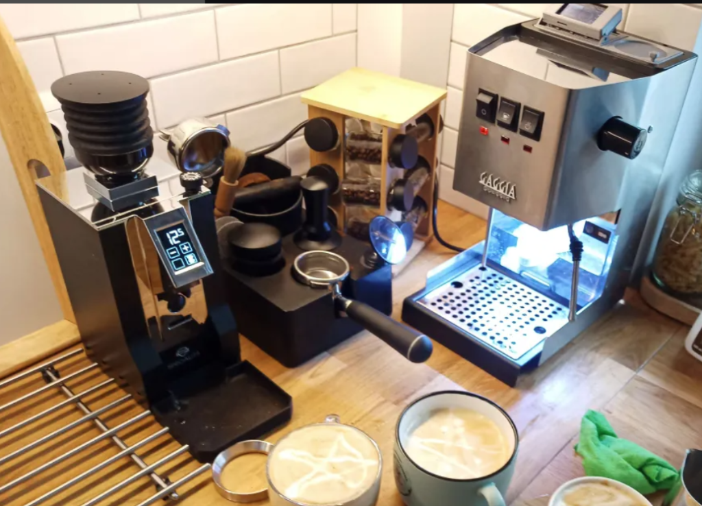
My setup before:

My setup after:

Orders
Kit
https://diy-efi.co.uk/product/gaggiuino-v3-pcb-kit-for-gaggia-classic-pro-evo – at the time peakcoffee had 4-8 weeks backlog, diy-efi had no backlog.
Ordered on January 26, 2024. Received on 11 February. Still, only half of the items from aliexpress arrived, so I still have to wait. I still worry if I have everything.

I am not sure how duty payments work, but I am also under the impression that peak-coffee wouldn’t result in an additional 170 Polish Złoty ($40) duty charge I had to pay to customs authorities. So even if kit+delivery was ~the same, if you are under a very tight budget peakcoffee may be cheaper overall.
I just had to pay extra cash to the mailman when I received the order. But it may be more complex – you may need to supply additional documentation to customs before the order is cleared – e.g. I had to provide the form for shades of coffee PID order also from the UK (which I ended up selling).
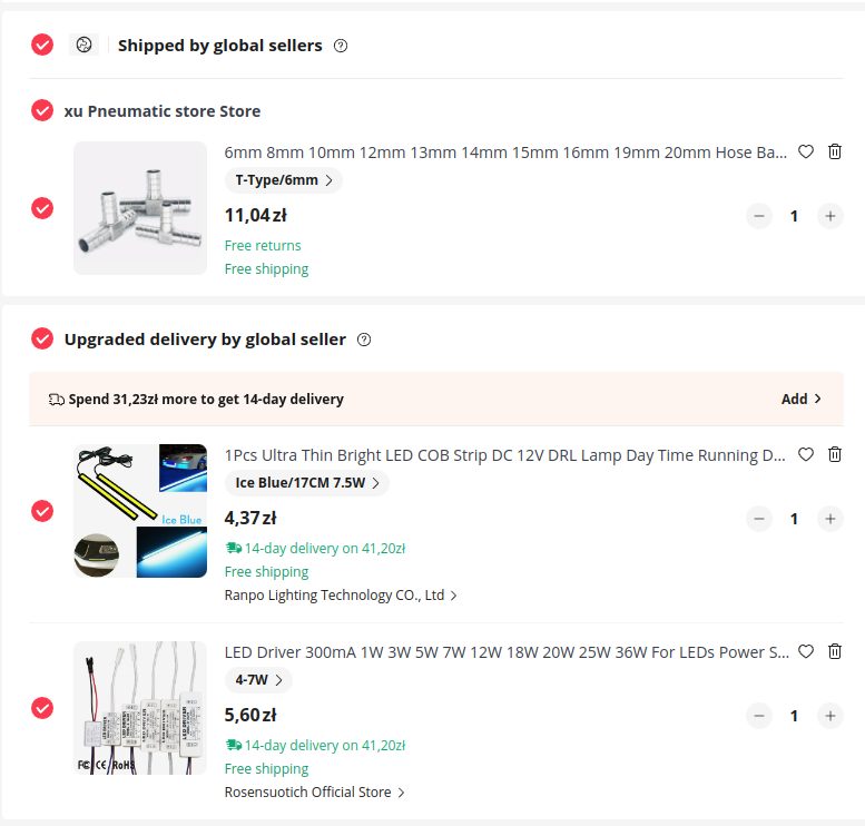
Spade connectors
Juun on Discord mentioned I need them.
https://www.aliexpress.com/item/1005003370887909.html?gatewayAdapt=glo2nld4itemAdapt
https://www.aliexpress.com/item/1005003373525650.html?gatewayAdapt=glo2nld4itemAdapt

You need a special crimping tool for those angled connectors. I really wanted to use them a few times (limited space issues), but I didn’t find a way to crimp them with the tools I got, so I ended up just using straight connectors everywhere. So if you don’t have a special tool to crimp angled connectors just get straight ones. As I ended up not using angled connectors, I had to buy extra straight connectors later. But if you want to have a clean install you should use angled connectors.
Custom wiring
Compatibility on the gaggiuino site ( https://gaggiuino.github.io/#/?id=compatibility ) for my model RI9481 recommends custom wiring.

Also if you do custom wiring don’t skip reading the “stock integration” page – https://gaggiuino.github.io/#/guides-stm32/3pln-stock-wiring-integration. Marking connectors with a sharpie prior to installation like in the stock integration is helpful. A lot of information on that page is also useful for custom wiring setups – e.g. Understanding what each connector means.
ECO switch modification
https://www.youtube.com/embed/WNs3uSLA4Ts?start=99&end=151 – video recommended on the Gaggiuino website.
Do not order any parts based on this video – the video was only about the spring removal, I understood I was meant to buy other stuff he discussed. This other stuff is already covered by the custom wiring.
I would recommend to not order a new switch – just use your stock one with removed spring like seen in minute 2 of this video.
Simplified led
DIY-efi had a longer wait time for tofnled board – no boards on the stock with month+ waiting time. This is just an LED light without connection to Gaggiuino for less than $10 (no water level indicator inside Gaggiuino).
1. Driver 4-7W
https://www.aliexpress.us/item/2251832620180796.html
2. LED 7.5W (not true 7.5W but get it anyway)
https://www.aliexpress.us/item/2255800740450307.html
3. OPV tube + pump intake tube consolidation via 6mm Tee. Highly recommended as this will give you an extra hole for the LED wire. Plus it looks a lot cleaner
https://www.aliexpress.us/item/3256805839664365.html
Install video of a similar led setup:
Install process is:
- T split tubing like in tofnled install docs ( https://gaggiuino.github.io/#/accessories/tofnled )
- Attach led with double-sided tape under the water tank
- Connect the LED cables to the driver cables by color (ideally “Western Union” splice and solder) and add insulation.
- Connect led driver cables to power – one cable on the line, one cable on neutral. You can connect it either to the pin or anywhere within a loop – I added it to one BN connector, as my areas with QC connectors were already very cramped

Tools
I have standard hex keys, screwdrivers, and spanners at home.
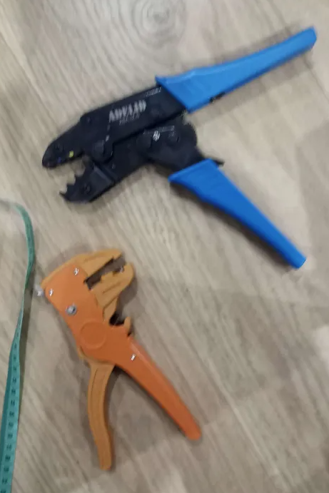
Ordered extra tools just in case from Ali – crimper and pliers:
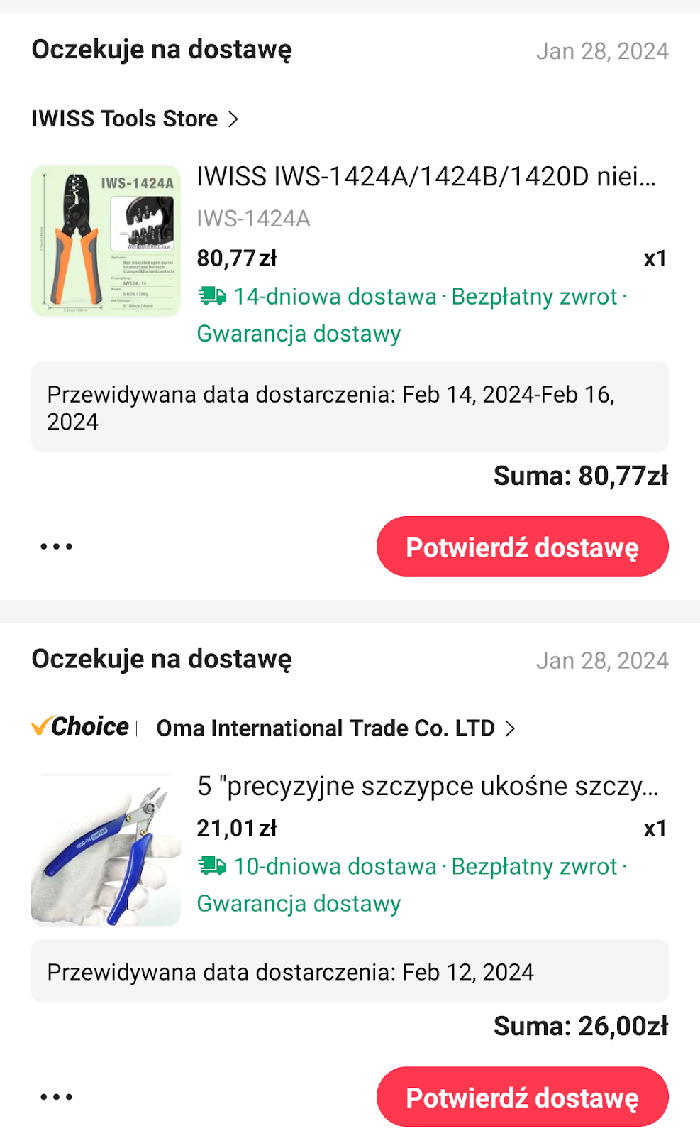
Pliers ended up being useful, but that crimper wasn’t great – it couldn’t even handle BN connectors I had to crimp – get a different one discussed later.
No additions – weights.
No built-in weights. The setup is intimidating already as it is. Predictive weights reportedly are within less than 2 grams of real weight and I already enjoy my slim drip tray from shadesofcofee – more space for big lattes I like to do.
I plan to upgrade to proper tofnled, scales at the time I will be doing the upgrade for the new Gaggiuino 2024 version ( https://www.youtube.com/watch?v=J4AyUoflVUU ) in the future. The Gaggiuino team is not sharing planned released date – the circulating meme is “next Monday” – same as when my weight loss journey will start – always next Monday.
Also, people sometimes do group-buys for ready-made kits for scales on the marketplace channel on Discord – e.g. example of such buy for scales: https://discord.com/channels/890339612441063494/1199712536174542890 . I’m hoping such group order will come up soon for GCP as well.
3d printing
As far as I understand, board housing is not needed in ECO models – ECO board housing will be re-used.
Unless you have already done some 3d printing I would just buy it from a site like espressio. I had to do a bit of manual fiddling, e.g. I had rotate the model, otherwise printing failed. Even if the printables description said I don’t need supports I had to add them. This is all probably due to the specifics of your printer (also I had to convert STLs to gcode for Ender printer).

Official docs list using filament for assembling the lid. But I didn’t have the solder, as I ordered a kit. What worked for me was just heating up the end of the nail with a lighter and pressing it in. I used M4x6 screw and 1.6×30 nail.


Retrospectively the screen enclosure I printed didn’t work and I ordered from espressio – see explained later.
Total cost
I would assume the total cost, including tools, shipping, 3d printed parts, duty payments, and extra things I bought to be around $400. I bought quite a few things I didn’t end up using and ordered more “just in case”, especially from aliexpress. You can try borrowing tools, but IMO it’s hard to go below $250, especially with the kit route.
My machine cost $350 (2022 model from the outlet, arguably better than 2023 Evos), so at the total price of ~$700 you are getting things that are really comparable just to Decent for $3000.
Important piece of the “cost” consideration is the time for install – at least 1 day to prepare and research, 2 additional days for install if you never done anything like this. To be honest, I consider it very cool to go through the project like this – e.g. I am not afraid to change light switches in my house any more.
People, who claim “meh, you can do it in a couple of hours” probably are not dealing with custom wiring and had prior experience installing things like a PID.
I think I have everything
Everything is probably completed (16 February 2024), one final part arrived yesterday.
I worry the most about whether I have enough cables. But I have a good electronics store nearby, so I don’t think I will have to wait weeks for something again. Cables linked in BOM are special rated for 200 degrees celsius, so you can’t just grab a random cable from the store.
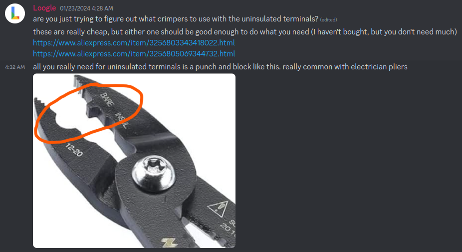
I think I’ll have to buy another crimper – I ordered the crimper listed in “Boiler Terminal Crimpers” in the bill of materials on https://gaggiuino.github.io/#/guides-stm32/3pln-custom-wiring?id=alternate-components – but it’s only for uninsulated connectors. When you crimp, you need to have a crimper that exactly fits the wire (solid vs stranded and size) as well as an insulated/uninsulated connector.

Completing control loop
The first step is completing the control loop – described in https://gaggiuino.github.io/#/pcb/singleboard.
Don’t look at the colors of the JST wires you got. Look at the input/outputs on the diagrams. You may need to take out some JST connectors like in this video: https://www.youtube.com/watch?v=nRVhPhfdawg
The cables are really tiny and I was nervous if I did the proper connection. Technically you can rely on just heat shrink tubing, but I didn’t feel it was secure enough. I gave up and bought a solder. https://www.youtube.com/watch?v=Zu3TYBs65FM is a great video about how to connect cables with a soldering iron.

SSR connector gave me a bit of trouble. Diagram says spade connector, but I don’t know how I am supposed to screw in that. I used a fork connector. I learned later that spade and fork connectors are referred to differently by different people in different countries. So when the wiring diagram says “spade” it means what some people refer to as a “fork”. When the wiring diagram says QC it is what some people refer to a “spade”.
SSR connection didn’t work out of the box. Finally, I had to buy an extra crimper. When crimping such tiny cables, strip more at the end and bend the exposed wire before crimping. Don’t try to crimp straight cable with a little bit exposed as you got in the kit. Basically strip 4x more than you need for crimping and bend it twice before crimping. For tiny cables, you need to make the crimped cable wider by bending it.
Completed version of the control loop:

Proper crimper and cable strippers I got after some fail without them (and extra fork connectors I used):

Vibrations
My machine vibrates a lot, so I wrapped pressure sensor in this foam: https://www.leroymerlin.pl/produkty/budowa/izolacja-budynkow/welna-mineralna-styropian-izolacja-akustyczna/izolacja-akustyczna/izolacja-akustyczna-i-termiczna-5-mm-25-m2-polifoam-45746792.html. Polietylen XPE is rated for 80 degrees Celsius. I’ve heard people putting some random foams in, but I would be nervous about putting anything not rated for higher temperatures – even if it’s not touching the boiler, ambient temperatures inside the case can get high. My material is not an ideal choice either, but there’s no officially recommended foam for Gaggiuino.
I spent 2 hours looking for something at local hardware stores. I went to the construction shop and asked for the small sample claiming I wanted to use this insulation for my house and wanted to run it by the construction crew.

I do enjoy this emoji after hanging out on Discord – type “:kekw” in chat and the autocomplete will complete to “:4566_KEKW:”
Starting setup
Before cutting wires
Mark connectors like in “Stock Wiring Integration” – it definitely will be useful for understanding what’s going on.

After removal

I heard the recommendation to not totally remove all cables, but leave the pump, grounding, and thermal fuse cabling in. Then the pump is a starting point for wiring on the back, the thermal fuse is a starting point for wiring on the boiler side, the PCB is 3rd point and you just connect those 3 points together. That worked well for me, but the drawback is that you will end up with a bit different wire colors than on the diagram. If you have printed the wiring diagram mark color differences on the diagram – it will definitely help and I wish I did it from the start.
Thermostats and thermal fuses
You can remove both Thermostats with 17 spanner. The upper thermostat can be replaced by a resettable thermal fuse. The resettable thermal fuse is an optional upgrade to the stock thermal fuse. Thermal fuse is that silicone cable touching the boiler at the top. Resettable thermal fuse AFAIK is only a minor improvement. The bottom thermostat will be replaced by a thermocouple (little cable with a small screw at the end you got in the kit). Both thermostats can be thrown out pretty much.
The thermal fuse is just there as an emergency shut-off when the temperature gets too high, so that’s why this cable is touching the boiler and we’re leaving it as it is. There are two thermal fuses – one at the boiler, and one at the pump. We keep them as they are, as they are important safety features. This is the boiler thermal fuse (you can identify it by a little bit of blue glue – don’t remove it):
I had thermal paste dried out on the bottom (brew) thermostat, but still “wet” on the top (steam) thermostat, so I just coated the thermocouple in the paste from the steam thermostat.
The top thermostat slot will be left empty if you don’t have an optional resettable fuse and that’s ok. You don’t need to measure temperature in two places. And that upper slot is a bad place to measure temperature anyway.
Start wiring with the pump

A lot of pump cabling can be reused. What you see on the left is the pump. What you see on the right is ECO housing – this is where the Gaggiuino board sits in and the previous ECO board used to sit in.
I had “high voltage” cables going left (towards the pump) and low voltage going right (in above picture just the thermocouple), separated by little plastic at the bottom of the housing – this is removable:
This is the dreaded eco board. The cables were cut and this can go to the trash:
Almost finished
In the heat of the install, I was moving pieces around a lot and was confused for a bit, so I didn’t take a lot of pictures – more pictures are later.

Problems after the first start
The screen didn’t work at first
My screen didn’t work.

To be honest, it was caused by my amateur 3d print. The screen worked outside of the printed case. I gave up on my own 3d printing and ordered from espressio. The problem was that the badly printed casing was pressing on the screen. For now, the screen is hanging a bit loose without fully closing and I’m waiting on proper 3d printed part delivery.
Switches didn’t work
Switches (brew, steam) didn’t work at first. Damn JST connector came off loose at the board. When I needed to unattach JST from the board, they were attached so hard that I was worried about damaging the board or connector by pulling (never pull by cables, pull by the plastic and wiggle it left and right).
When you have the ECO board some people give advice to get rid of the housing and use the 3d printed one. I would prefer such a solution. It’s a nightmare to take the ECO housing to access at the late stages of the build. I even redid the splicing of switch cables to avoid taking the ECO housing out, but after it didn’t help I reached for the board.
Some retrospective things
Electronic store
It really helped me to find a local helpful electronics store and don’t bug Discord with the most basic questions. However, I did ask a lot of questions anyway since I never worked with any wiring in the past (big thanks everyone for help!). An electronics store may help you and even run some multimeter tests. Big thanks to Artel in Kobyłka if you ever see this.

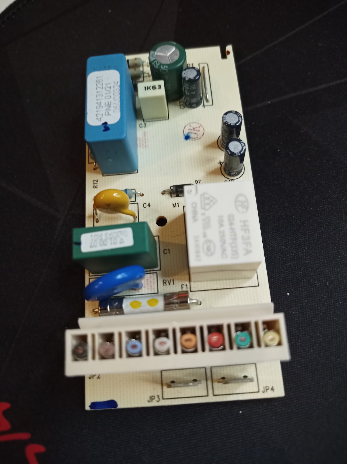
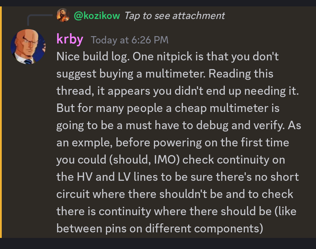
If you don’t have access to a multimeter at a friendly electronics store consider sourcing it. I winged it and turned everything on without a multimeter, but shorts can irreversibly damage parts:
Eco housing
I heard the advice to ditch ECO housing altogether and use printed board housing. That would work a lot better. It’s really hard to take out and access the ECO board right now. Eco board makes finding a place for SSR harder.
Colored zip ties
Colored zip ties – separating low voltage and high voltage wiring was easier by marking each type by colored zip-tie – blue for Low Voltage, Red for high voltage.

Yeah, the build didn’t come out as clean as I hoped.
Zip tie early and zip tie often. Make sure low-voltage cables with blue zip ties are not touching high-voltage cables with red zip ties. Different voltage cables touching causes interference and the machine would perform erratically.
Grounding cables ideally would go with high voltage, but as space is quite limited it’s OK for them to go near low-voltage cables.
Make sure any cables besides the thermal fuse at the top are not touching the boiler or steam.
SSR placing
SSR allows Gaggiuino to control a high voltage loop without that high voltage ever touching the board.

I don’t know how people can fit SSR at the back with the ECO board and funnel coming in a way. Without an ECO board you can fit it in an area when the ECO board is (this is what I’ve seen at non-ECO builds). I gave up and drilled a hole in a case.
In such scenarios, it’s important to add thermal paste on the back of the SSR – especially if it’s in a high heat area near the steam wand. Thermal paste was even recommended by Zerobit: https://discord.com/channels/890339612441063494/1200384353168011345/1209094457492766730
Retrospectively, I was trying to attach both SSR screws. There’s probably a way to fit in the back in the SSR area by attaching just one screw and SSR hanging at an angle. You need to get your own m4 screws, nut, and washer, as those don’t come in the kit. It’s challenging to attach the nut in a tight space, holding it with pliers worked for me.
Crimpers and strippers
The crimper I got from Ali didn’t work well for BN connectors. Basically, you need a crimper for BN (uninsulated) like in https://discord.com/channels/890339612441063494/1197369695519645837/1199194042228035594 and something for crimping insulated connectors.
I got a crimper and stripper like this bought at a local electronics store:
An automated wire stripper (orange) like this was very useful, but more of a convenience feature. I paid less than $20 for both of the above – cheaper models at the electronics store, but worked well. The cable crimper (blue) worked very well for me. This crimper above works only for insulated connectors, but you should mostly use those (the only uninsulated connector you use is BN connector and you should insulate it after attaching – e.g. with heat shrink tubing).
The crimper above worked really well for QC connectors (sometimes referred to as spade). Basically put the connector in, tighten Jaws until it’s held secure, insert the cables, and squeeze. Red connector for a single cable, a blue connector for two cables going into connector (color of insulation means the size of a hole with those) :

The hardest job was stripping those tiny (22AWG or smaller) cables that came with JST in the kit. For those, I ended up using some tricks with pliers – an automated stripper ended up cutting the cable alongside the insulation. If you see some wires came off with insulation cut it and strip it again. So I probably would skip automated stripper, as it can’t get the hardest job done. Watch some videos on “stripping tiny wires” on YouTube – e.g. heat up the insulation before stripping – if I applied this method from the start it would save me a lot of trouble.
There are 5 types of connections you need to use in the build:

From the left:
- White plastic, first from the left – JST, those will just plug into the board. Those should come in the kit, but you will need to connect the cables (splice to another cable and add a connector – e.g. fork for SSR). It’s OK to splice those tiny cables to thicker cables if you are wondering. Splicing cables means connecting two cables.
- Second from the left – female spade connector, sometimes referred to as QC. Those will plug into various parts of the machine like switches and into 4 big connectors (3PLN) at the board.
- Fork connector, Third from the left. Sometimes referred to as spade connector (yes, spade semantics are confusing). Those will connect to SSR with screw-on
- BN connector, sometimes referred to as butt connector, first from the right – those will connect two high voltage cables together, as AFAIK those shouldn’t be soldered due to added resistance
- Low voltage cable splicing – connecting two low voltage cables together. I used Western Union Splice and soldering – see Gaggiuino recommendation site – https://gaggiuino.github.io/#/learning/learning-sources
2 and 3 would use an insulated crimper like the blue crimper in the photo attached before. 4 would use an uninsulated crimper like https://discord.com/channels/890339612441063494/1197369695519645837/1199194042228035594
Good pliers
I was very happy with the pliers I got https://pl.aliexpress.com/item/4001146365274.html?spm=a2g0o.order_list.order_list_main.53.3f931c24PGZYR5&gatewayAdapt=glo2pol . It was definitely the most frequently used tool, especially you sometimes need to cut things in hard-to-access areas that regular scissors wouldn’t work. Given it’s $5 on Ali, it’s a very worthwhile purchase.
Transducer length
I ended up cutting the pump hose a bit too high. Because of that I couldn’t properly lay the transducer on the bottom of the case. The transducer’s ideal position is lying down on the bottom of the case.

I am considering re-ordering a longer piece of hose (see BOM) to put it in the proper position later, but the pressure seems to work OK (e.g. No sudden spikes like some people get – maybe that foam is saving me).
Insulation
I ended up using both heat shrink tubing and self-fusing tape. Sometimes one is better than the other, but 80% of the time heat-shrinking tubing is better. The biggest use case for tape over tubing for me was splicing differently sized cables.
You don’t need a heat gun for heat shrink tubing – a flame-less cheap lighter (see photo) works great (not a regular lighter, as it’s a higher risk of burning cables). I had to buy some smaller diameter heat shrink tubing than in BOM at the local electronic store for low voltage cables.

Don’t just burn one place – move around the lighter and rotate the cable. Be careful around at the edges, as if you hold it for more than 1 sec in one place it can still burn the unstripped insulation underneath. It happened to me once and I just added self-fusing paste there. Hold it a bit away from the cable like in the picture below (also included an example of smaller tubing I got for the low voltage cables):
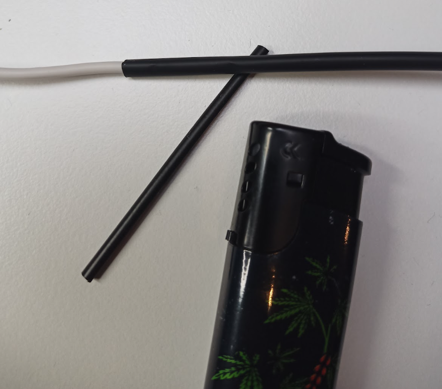
Diagram printing
Print a main diagram in A2 and others in A3. Having it at hand and being able to mark things with a pen is really helpful. E.g. put a mark on connectors you already put in and matching mark on the print. Even if you don’t have a printer, some local printing shops can do it for you for less than $10.

Soldering
Soldering is optional for kit installers, but very helpful. The part that gave me the biggest worry was connecting those very tiny cables that came with the JST. You technically can rely on just twisting them together and heat shrink tubing to hold them. But as you will be connecting things inside the quite limited space inside the machine it’s challenging to not pull on those cables.
Part-way during the low voltage wiring side I gave up and got a solder. You can do everything with the cheapest model that will run you for less than $20 including solder and materials. And you won’t constantly worry about “Did this cable lose connection”. I had the “pre-soldering” cables come off, but all soldered connections didn’t fail.
https://www.youtube.com/watch?v=Zu3TYBs65FM is a great video about how to connect cables with a soldering iron. Soldering cables is a lot easier than pins on motherboard, so after this video you should be ready to go – I promise you will think – it’s not that hard after all.
Cheap soldering iron I got:

I did my first soldering without turning the fan on and I felt dizzy. Open the windows and turn on the fan when you are soldering. That solder (wire in the middle above) will melt from touching hot iron (on the left) and add melted metal inside and around cables to fuse them stronger.
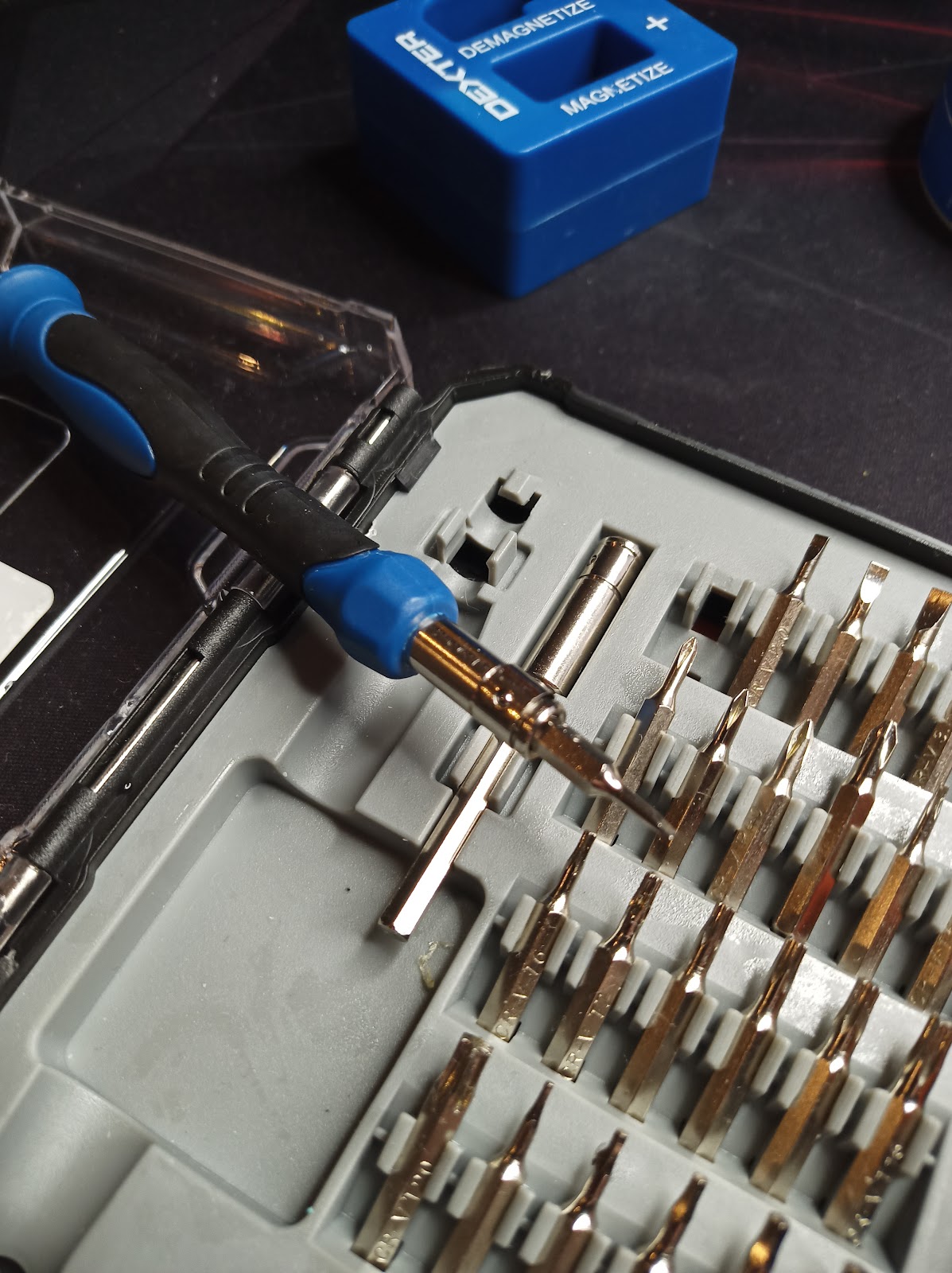
Tiny screwdriver
There are two tasks you need a tiny screwdriver:
- Removing screws connecting pump and eco board to the housing on the bottom back of the machine. You will need a magnetized thin, long screwdriver.
- And a very tiny flat screw to attach the thermocouple to the board (see second photo below).
This kit worked for me. I paid $15 for this:

ST-link
The old branch with a small screen is feature frozen. That means no updates are being developed for it. A new branch with a bigger screen and wifi will require taking Pcb out. This is just a speculation, as Gaggiuino team is keeping things confidential.
Stlink is for software updates for Gaggiuino.
So I skipped stlink for now, as I am near certain I wouldn’t use it before the next upgrade. And AFAIK the new upgrade has wifi software updates planned, so I probably wouldn’t use stlink ever. And wiring stlink is a bit annoying – pins are hard to access.
Other support threads
Always use discord search first. Very good way is to look via support threads with similar setups as yours. E.g. go to https://discord.com/channels/890339612441063494/996188987964268555 – look at people with exactly the same machine as you and read through questions and answers.
Discord search could use some improvement and if I find some time I’ll give it a shot and train a LLM chatbot on discord history and docs – I trained the customer support model for my work and it works pretty well.
Post-install
PZ
“Hey, my predictive weights are all wrong!” – you have to adjust the pz (pump zero) value in settings. There’s an official process to that and I recommend you to look at it: https://discord.com/channels/890339612441063494/1207175678722703410/1207760983485980674 . I just kept raising pz when the weight of my coffee was too high compared to the scale. When you stay within one profile that will work.
Settings -> System -> Click the number next to PUMP Zero adjust the value and click save

Profiles
For a typical Brazilian medium roast (https://www.konesso.pl/product-pol-6522-Kawa-ziarnista-The-White-Bear-Brazylia-Guaxupe-1kg-uniw.html) previously already dialed in – Londinium ended up working the best for me.
But you are not really Gaggiuining if you are not trying to extract light roasts with bloom profile, so this is what I am going to do next.
Steam purging
“Huh, my steam temperature won’t raise” – it’s caused by ~11-bar limit on pressure. If you see the steam temperature stuck around 120-130 degrees and pressure at 11 bar you need to open a steam wand for a sec and close it again.
Additional Links
https://gaggiuino.github.io/ – Gaggiuino website
Discord thread for my setup – https://discord.com/channels/890339612441063494/1200384353168011345
Lance Hedrick build – https://www.youtube.com/watch?v=V4pTFCGVlmQ
YouTube channel Whole Latte Love for how Gaggia machines work and how to disassemble them – e.g. https://youtu.be/N9i-EH7qXOc?t=262
Engineering mindset youtube channel for a refresher on some theory useful within the context of this project – e.g. https://www.youtube.com/watch?v=JBpQ9Fodz_Q

Leave a comment